Electronic Multi-port Fuel Injection Conversion
Through out this site there are various references to my planned fuel injection conversion. For instance look at the Engine link to see details about the intake manifold fabrication. It is now August of 2003 and the conversion is fully underway. Actually a bit under the gun to get it installed and sorted out in time to make the five hour drive to the The British Invasion in Stowe Vt. next month.
Installation of the Electromotive TEC-3 system is now the project. Choosing the control system was a bit of a struggle. Torn between the very low cost (MegaSquirt @ $300), a medium priced controller (Simple Digital @ $1000), or the very high end (Electromotive @ $2,000), I chose the high end. An unsuccessful bid attempt to purchase the MegaSquirt forced the decision. I could accept the limited capabilities of the MegaSquirt for it’s bargain price but when it came to a full blown system, the TEC-3 is the clear winner. I also used the excuse that as an auto parts professional a wealth of knowledge would be gained. In fact I now have a clear insight into the inner workings of electronic fuel injection. Just reading Electromotive’s 176 page manual on the TEC-3 is an education (see getfuelinjected.com). Anyway here we go with the conversion.
The conversion is much more involved than at first glance. Starting with the gas tank, provision must be made for a return line, a high pressure fuel pump and a filter. A crank position sensor located on the balancer / flywheel or a half speed sensor on the distributor is required. Sensors such as coolant temp, knock, throttle position, manifold air temp, manifold air pressure, and oxygen are needed. Addition of an idle air control is also necessary, not to mention six injectors, a pressure regulator, air door, air cleaner, fuel filters, and a ton of wiring. The TEC-3 is a distributorless system using a DFU (Direct Fire Unit) so a bank of coil packs are also required. I’ve probably overlooked a few things at that. What I’m trying to say is that the conversion is rather complicated and probably not for the faint of heart.
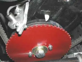
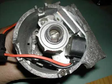
The photo on the right shows the crank sensor and timing wheel fitted to the front of the harmonic balancer hub.
Fuel Injection Update
On April 24th 2003 the TEC-3 engine control system from Electromotive, was finally ordered. I must admit that I’ve had my eye on this high end system for the past year but between the cost and the fact that the car was in pieces kept me at bay.
A year ago, over the winter, I built a multi port style intake for the TR6 based on the generous sharing of plans by Total Advance (unfortunately the link is no longer up).Thank you Total Advance for supporting the TR6, best to you in the new endeavor. In case you missed it, Total Advance offered the TR6 manifold with injectors and an air door for $1500. Their ECU was somewhere around $800. Considering what you got, it was a reasonable price. Trouble was, that most TR6 enthusiasts wanted the benefits of fuel injection at a lower price and with a plug and play installation.
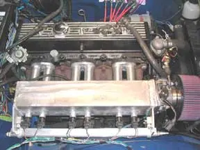
Fuel injection intake manifold with injectors trial fitting.
(First design)
For the past year my intention is to use the TR6 as a fuel injection test bed starting with the multi port manifold. Since photos of the manifold appeared on my site, several people have contacted me remarking that there is no inexpensive method to fuel inject a TR6. By acquiring the TEC-3 system I will be able to experiment with just about every type of fuel injection, both multi port or throttle body styles. The push is now for the high end multi port system but I also want to experiment with a very reasonably priced throttle body system as well.
May 1, 2003, Originally I had planned to mount the 1/8″ thick sprocket wheel behind the balancer but there simply isn’t room. The timing cover’s front crank seal nearly fills the void on the back of the balancer leaving little room for an additional sprocket. Not to say it is impossible but it would require considerable machining and welding. The new sprocket looks absolutely huge being ½” larger than the balancer. Adding the sprocket precludes using the fan shaft extension and the original plastic fan. In the process of converting this car to an electric fan, I installed one of Ken Myhre’s fan spacers, eliminating the fan shaft extension shaft and the plastic fan. The spacer was Ken’s prototype and ½” thick. I also have one of Ken’s later spacers that is 9/16″ thick. The thicker spacer is just enough to hold the sprocket off the front of the balancer and its bulging rubber insert. The new timing sprocket has a 1″ mounting hole and the TR6 uses a 5/8″ fine thread bolt to hold the balancer in place. A thin bushing to center the sprocket on the bolt was fashioned from aluminum.
My first thought was that it would take a spacer a bit thicker than 9/16″ to keep the balancer’s outer ring from disturbing the sprocket. An evening was spent on the lathe building a new spacer that was 5/8″ thick. Rather than using a centering bushing, a 1″ boss is part of the new spacer. Building the spacer is not as straight forward as first thought because it must be drilled perfectly to accept the two drive pins that stick out of the balancer. The thick spacer is done except for drilling the two dowel pin holes. Now I’m thinking about cutting its thickness down to 9/16″ after a trial fitting. The sprocket must run within .007″ true so the integral boss is probably worth the effort. I believe Ken will be able to supply this style spacer should anyone be interested. Once the sprocket and magnetic pick are aligned the sprocket and spacer will be drilled for a couple of small allen head screws to ensure the relationship doesn’t change.
May 10, 2003 The dowel pin holes are done in the sprocket spacer but not without much fussing. Drilling the two holes was painfully slow due to my lack of experience on the milling machine. I’ve now learned a valuable lesson about setting up the milling machine and how important it is to plan ahead. The accuracy of the spacer is superb with it dropping in place with a minimum of effort. The dowel pin locations are within a couple of thousandths of an inch.
Next up was to drill and tap the spacer for two socket head bolts that ensure the sprocket doesn’t wander. Picked up a couple of stainless 10-24 socket head screws for the job. Drilled and planned to tap the spacer for the screws. That was the plan anyway. And did it go awry! After drilling, the first tap snapped off in the spacer. Managed to remove it with a punch only to break another tap. The second hole was going better with the tap almost all the way through when it too broke off. It’s been years since I broke a tap and now I’ve broken three in a row! This time they are too well entrenched to remove with a punch. Cobalt drill bits wouldn’t touch them either. I think the diameter is just too small to handle the torque of tapping 9/16″ deep in steel. Clearing the tap and even completely removing it to flush the new threads while tapping wasn’t the answer. Tomorrow I plan to drill two additional holes and tap them for much larger screws. I don’t want to make another spacer.
Drilling new holes and tapping to ¼-20 went without a hitch. The tap was run just deep enough for the bolts as it was really taking a lot to turn it. It has just dawned on me that the piece the spacer was carved from was probably a very tough cast steel. The parts have now been cleaned and painted with etching primer, a silver, then a top coat of a color close to Electromotive’s purple.
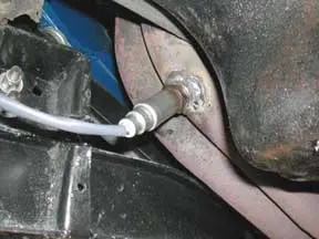
Adding fuel injection or just adding an electric fan requires the addition of a coolant temp sensor or fan switch. The TR6 coolant temp sender is straight thread 5/8″ fine rather than the more common pipe threads used in today’s cars. Fortunately 5/8″ fine is the same pitch as 3/8″ pipe thread making the conversion pretty easy. Just below the thermostat the hose nipple on the passenger side was removed. The socket was tapped to 3/8″ pipe and a 3/8″ street tee (NAPA WH 3750×6) threaded in. The street tee is male on one end, female in the center and female on the other. A ½” hose barb with 3/8″ pipe threads (NAPA BK 660-1503) was screwed into one end and the sensor screwed into the center of the tee. Substituting for the sensor temporarily will be a fan switch (NAPA ECH FS118) that closes at 211 degrees ascending. For now it will control the electric fan relay but as the project progresses it will be replaced with a GM style coolant temp sensor (NAPA ECH TS4015). For photos see Spring 2003
May 14th, 2003. The timing sprocket and magnetic pick up installation is done. The steering rack is tightened down, the frame cross brace reinstalled -right side up this time, and the radiator installed. Glad I took the time to do the timing sprocket now as it is a time consuming project.
May 15th, 2003. Started checking the wheel alignment. At this time all I want to do is get the alignment close enough so my alignment shop can finish it. The front toe is at 1/8″ so it will be fine. Left front camber was adjusted by adding three shims behind the lower control arm mounts. Right toe was off on both sides. One shim to the outer mount on the left and two shims to the outer mount on the right. Rear wheel camber looks pretty close however the right rear body height is high and the left front low. It is possible that there is an extra spring spacer in the right rear causing the problem. Also possible that the left front spring is weak.
June 2003. The car is on the road! So far so good but still some loose ends to tie up. The alignment was done in my garage with a string, a tape measure, and a level. Not bad but the handling still isn’t what it should be. The weather is nice so it will be drive rather than work on it for a while.
July 2003. Been driving the car regularly without a hitch. By that I mean nearly everything is working! Ok so there is a slight leak from the clutch master cylinder. Just enough to create black spots on my new tan wool carpeting and even spots on my new white Nike’s! Late in July I finally had a rainy day off and pulled the master to rebuild. Previously I had ordered a kit for the job. Upon disassembly found that the bore of the old master was beyond a mild honing. The bottom was badly pitted perhaps caused by some standing water? Anyway a new master was ordered so why not work on the fuel injection conversion in the meantime.
August 2003.
Just visited the British Invasion web site about the big Brit show in Stowe VT on the weekend of Sept 19th and realized time was getting short. If I wanted to run the car with fuel injection I’d better get going. While waiting for the clutch master and enduring endless weeks of rain and humidity, the project restarted. A triple coil pack (called the DFU by Electromotive for Direct Fire Unit) was mounted to the left inner fender well. White plastic material about an inch thick used in boat building was cut on a band saw into fairing blocks to fit the curvature of the inner fender well. Originally I had planned to mount the pack on the shelf alongside the windshield wiper motor but decided the inner fender was a better location for plug wire mounting and had no interference from cables.
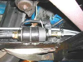
The fuel supply system consists of a prefuel filter, high pressure fuel pump, final filter, pressure regulator, supply and return lines. At the tank outlet a shut off valve and a 3/8″ hase barb was added to supply the in line fuel pump. The high pressure pump (NAPA P5000) is mounted low on the frame just ahead of the rear axle. Between the tank and the pump is an inline filter (just out of the photo to the left, NAPA 3270) designed for diesel fuel. This filter is very coarse and will only preclude large debris protecting the pump but not restricting it’s suction.
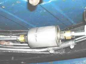
The pressure output line from the pump is a five foot section of 3/8″ steel brake line connected to a common GM fuel injection filter (NAPA 3481). Special adapters, (NAPA WH 1446) are used to mate the 3/8″ steel brake lines to the filter. The steel line continues forward terminating to a 3/8″ hose barb on the right hand inner fender. A short section of high pressure 3/8″ fuel injection line connects the line to the fuel rail. The fuel pump is whisper quiet. Connected to the rear of the fuel rail by 5/15″ high pressure hose is the regulator aquired from a Datsum 280ZX. Bypass fuel from the regulator is returned to the tank via 5/16″ steel brake line. The return is connected to the tank via a welded 1/4″ pipe thread bung. Inside the tank is a 90 degree elbow aimed at the bottom to keep fuel from splashing and picking up air bubbles. Perhaps I should have also added some internal baffles to the tank to stop fuel starvation on long hard left hand turns?
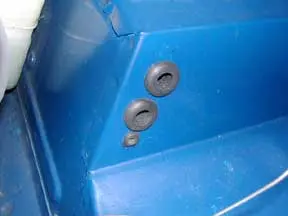
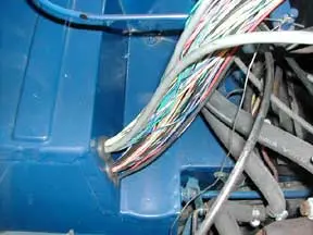
Holes were drilled and grommets added to bring the two main wiring harnesses out from under the passenger foot well. Two 3/4″ holes and a 3/8″ hole were drilled and all the connecting wiring pulled out through. The fit was really tight but all the wires fit with some persuasion. As it turned out quite a few wires were pulled back (not needed on this installation) so perhaps just two 3/4″ holes would suffice. In the hollow under the hood latch three relays and the MAP sensor (NAPA 3-1961) was mounted. Alongside them on top of the shelf a four circuit fuse panel (NAPA FB6263) was mounted. Seeing all those wires make me wonder if the alternator (already upgraded to a Jaguar unit) can handle the extra load. That extra load being the previously added electric cooling fan and the new electric fuel pump, coil packs, and injector bank.
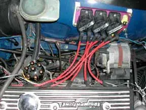
Today is August 13th and much of the wiring is done. Three relays, fuel pump, coil packs, and injectors are wired. Although the intake still needs some work it was placed atop the carbs/air filter and a harness built for injectors, idle air control motor, manifold air temp sensor (GM style NAPA TS5100). The harness is intentionally extra long as I’m not sure about routing etc. Once the manifold is finally fitted the harness can be adjusted. On the left side of the engine the coil packs are wired and the coolant temp sensor connector added. The knock sensor connector still needs to be added once its placement is decided. I was a concerned about mounting it on the valve train side of the engine thinking it may be noisier and give false readings but was told that the sensor actually looks for particular frequencies. Guess we will find out. The knock sensor is a GM style (NAPA DKS209). Added to the harness for future use is the shielded lead for the cam sensor. At some point next year the cam will be upgraded and at that time I can fit a cam sensor to the timing cover.
I’ve done a fair amount of research on cam profiles and now think a custom grind is in order. One of the attributes of the TEC-3 system is that it is supposed to give a decent idle even with a radical cam. Will keep you posted.
The plug wires from NAPA are an 8mm Belden high performance universal set. The wires are cut to length and distributor ends added. These red suppression wires look great and will handle anything the distributor less system can throw at it.
query to Electromotive answered my question asking if the ignition system could be run without the fuel injection. They said sure it will run but wondered why anyone would want too. I do because there is still a fair amount of work to be done to the intake manifold. Bungs need to be added for vacuum for MAP sensor, the brake booster, and the manifold air temp. The throttle body from a Ford 5.0 will need a heavy plate welded to the intake mouth to hold the mounting screws. Some sort of throttle cable will be required. Some work on the milling machine is needed to make an adapter plate to mount a GM stepper motor style idle air control to the ford throttle body. The fuel rail itself needs a method of securing it in place. Time is running out to get all this done and tested before taking off on a five plus hour trip to Vermont.
August 15, 2003. The plug wires are now fitted to the coil pack and trimmed to length. Perhaps a tad long but they can be shortened after removal of the Crane coil. Guess I need to think about either running a bare distributor cap or making some sort of cover. Ran the last of the ground wires and made the new fuse block high amperage final connection to the battery. And THEN turned on the key to see what the computer did. It’s little red light blinked to green saying all is well. Also checked to see if the fuel pump relay pulled in supplying 12V for the pump (after the wire is run) and it worked properly shutting itself off after 8 seconds without the engine turning. Another relay pulled in supplying power to the coil packs as well and a third relay supplying the injectors. So far everything is working according to plan! Under the dash there is more work to be done. Indicator lights and various switches need to be discreetly installed. I think by connecting the laptop to it right now I can get the ignition system running.
Wonders never cease. I pulled out the choke turned the key, and it was running on the distributor less system! Yi Ha!! Plugging the laptop into the TEC-3 and observing the “Monitor Engine” view showed just how things were functioning. Displayed was engine timimg, a tachometer, MAP sensor readings, battery voltage, and coolant temperature. Of course there were other readings displayed but they weren’t relevant as yet. The car ran better than it had in years! The idle was vastly improved. The previous ignition system had been a Crane XR3000 system with a Crane high energy coil installed a year or two ago. The engine ran so much smoother that I retrieved the old distributor cap and verified that the firing order was correct. It was, however looking the cap over carefully revealed the center post was nearly eroded away to nothing. The Crane coil put a lot of power through that post so the cap should be checked frequently. I have put about 140 miles on the car now and the ignition system is functioning perfectly.
A bung has been welded to one of the two exhaust head pipes. It certainly would have been better if the sensor could monitor all six cylinders however this car, being a ’75, has two seperate pipes running all the way back to the muffler. Next year my hope is to change the system to a single 2.5″ pipe that the O2 sensor can be mounted. The sensor is a universal heated four wire Bosch, number 15732 (where else – NAPA).
Sept 2, 2003. Tonight marked a milestone. Aaron Cropley, another TR6 owner, came over and we removed the carbs and fitted the fuel injection manifold into place! Yes it fits! Must admit there was a tad of trimming required to allow it to settle into the valleys created by the exhaust manifold but it does fit.
Prior to installing the manifold I charged the fuel rail with 35psi or air and connected the wiring harness to the car. Remember the car is running on the TEC-3 computer even though just the ignition is presently controlled. The computer thinks it is running the injectors so when we hooked the manifold to the harness while running, it fired the injectors. With a small hose as a hearing aid device I could listen to each injector fire its charge of air. Bad news was that #3 was leaking badly and not firing with the snap of its brothers. Next we filled the fuel rail with injector cleaner, put 35psi of air behind it and aimed the manifold into a handy trash barrel. Number 3 was still acting up. I’d hoped that the injector cleaner would free up a gummed up injector. So far no such luck but will try it again after the cleaner has had a chance to work its magic.
Test firing of the injectors went rather smoothly considering we are using donated free VW Jetta Digifant injectors. Throttle linkage is still under consideration. Steel fuel lines need to be run the last couple of feet for pressure supply and the regulator/return circuit. Running the tubing should be should be pretty easy with the manifold removed. Just dawned on me that the manifold in all likelihood will need to be removed to replace a faulty injector. The rear of the fuel rail where the return line attaches needs to be shortened as it is very close to the firewall. Cutting off an inch and installing a 3/8″ pipe thread 90 degree elbow to 5/16″ hose barb will certainly provide the required relief.
The injectors presently installed are VW number 280150902. They are the same as used in a 1992 VW Jetta with a 1.8 Digifant injection system. One of the reasons (besides the free price) is that they have a long conical snout and I hope that they will spray in a more concentrated stream than the standard pintle stye injector. These injectors are rated at 18.75lbs of fuel per hour, each one capable of producing 39 HP! The injectors are a grayish blue color and cross to Napa’s number 2-18237. Tomorrow I’ll be looking for some more used free injectors.
The following morning a trip was made to my favorite self service junk yard. The yard was busy crushing cars and large sections of the yard were empty. Just as I was about to give up, I noticed an intact Jetta way up in one corner. Twenty minutes later I had four more injectors. A nearby Buick V6 gave up it’s injector harness for a possible future project. Total cost $5!
Throttle linkage was actually quite simple. A 1/4″ steel rod runs from the original firewall lever to an adapter plate on the 5.0 Ford throttle body. The throttle body end of the shaft has a threaded stud welded on that serves as an adjustment for a ball socket. A little math and the original TR6 gas pedal easily goes from idle to wide open.
The TEC-3 computer has what’s called a “Tuning Wizard” where you enter basic facts about your installation such as number of cylinders, approximate horsepower, injector ratings, red line, and a few other pertinent facts. The Wizard then generates a profile that will serve as a starting point for fuel injection tuning. Turned the key and what do you know? It runs!! Not well at all but it did run.
September 2003. The “The British Invasion”, the biggest British car show in the Northeast, was slated for the weekend of September 19th in Stowe Vt. It was the show that I’d been hoping to attend for the past three years and the car was far from ready for a five hour drive. The car was running as a fuel injected but needed a lot of more work.
Nearly every waking moment of early September was spent at work or working on the car. The idle was incredibly rich – so much so that the fumes would quickly give me a headache even with an exhaust hose piping most of the fumes outdoors. Shortening the injector pulse duration times leaned out the idle but robbed the top end of fuel. Don’t get me wrong, tuning the TEC-3 controlled system is not all that difficult but without a dyno, very time consuming. In the meantime I was learning a lot about the inner workings of modern fuel injection. I’d make a couple of changes then take a ride around the block to see if I was on the right track. Some trips were only a lurching bucking hundred feet or less then back up to the garage hoping the neighbors hadn’t noticed. After a few evenings roaring around, it was drivable. Still running rich but drivable.
At the same time there were a lot of other things needing attention before making the trip. There was no crankcase vent system and connecting the aluminum valve cover tube to to the throttle body put gobs of oil into the incoming air stream. Also since raising the compression ratio to 9.5/1 the valve adjustment screws were nearly backed out all the way. Enough so that they would rap against the underside of the stock valve cover. The car hasn’t been aligned since going back on the road after its restoration. I wanted to set the rear camber before taking it for a four wheel alignment. The u-joints are original and I’d hoped to change them before making the trek. Not to mention the car was a mess and the paint needed to be buffed out.
In the week leading up to the trip, Richard Goode’s oil separator arrived. It was the perfect solution to my crankcase vent problem. The separator kit included everything for installation however I had already mounted relays and the MAP sensor where Richard said it should be mounted. It would fit if mounted at an angle on the left side inner fender just in front of the windshield washer reservoir. A 3/8 steel line was run behind the cylinder head to route the separated oil back into the crankcase via a plate mounted where the mechanical fuel pump once lived. It was a nice neat installation until it was time to close the bonnet. As the hood came down the prop rod ran smack into the separator. Removing the rod allowed the hood to close so it would have to do until after the show.
The shortened push rods were another matter. Nick Gemas from neighboring New Hampshire had two sets of shortened push rods, one shorter than the other. We guessed at the length and found that the chrome moly push rods were way too short. Nick jumped to the rescue and sent the proper ones quickly. They are a perfect fit. Thanks Nick. Here we go shifting at 5K plus!!
While waiting for the second set of push rods, an afternoon was spent wet sanding the clearcoat with 2000 grit paper. Later that night a friend came over and buffed it to a great shine.
Meanwhile various test runs were made until I felt the injection system was at least drivable and wouldn’t damage the engine with a lean condition on the trip. Still running rich but she would get to 5K in an instant! I’ve owned this car for years and usually shift at much lower rpms. This was fun! The idle was still a problem with number six cylinder running rich. First thought was that the injector was leaking by, just dumping fuel to number six. The idle would actually pick up when the injector plug was removed. Pulled the fuel rail and replaced the suspect injector. A little better but still rich. It dawned on me that because number six was last to get air from the throttle, each injector ahead of it richened its incoming air. By the time the incoming air reached the number six runner it was already heavy with fuel. Time to ponder a different manifold design.
The big tuning clue came after I added some optional potentiometers, one for mixture and one for ignition advance. While driving you could twist the knob to see if things were better richer/leaner or advanced/retarded. I learned that what I’d believed was a rich condition on acceleration was in fact a very lean condition. The Volumetric Efficiency table was adjusted accordingly. The acceleration was blistering but overall the cruise wasn’t very good. Have I mentioned that the system also does data logging? It sure does so you can make that trip around the block or down the track and review it at a later date. Really cool and handy when tuning. The present settings would have to due until after the trip.
September 19th and it was time to head to Stowe and no time left for replacing u-joints and getting an alignment done. Other than that the car was pretty much ready, untested but ready. On Friday morning we joined up with Aaron Cropley and Kim in his TR6 and Phil and Amy Shelton in their MG B. First stop was about twenty miles away for the MG to fill up and me to learn that my battery was flat and wouldn’t turn the engine over without a jump. The alternator was a Lucas but had been replaced with an uprated Jaguar unit. Still, added to the electrical load was a computer, electric fuel pump, sensors, injectors, electric cooling fan, and coil packs. My hope was that the alternator could stay ahead of the load. I prayed we would outrun the forecasted rain and be there before needing headlights and wipers.
Last minute tuning was done on the fly. Phil jumped in and drove while I ran a laptop monitoring over a dozen engine functions. Leaner was the order of the day. Phil would floor the car as I leaned it out. Leaner was better. The car was actually starting to run quite well. After about 50 miles of these acceleration bouts we had it pretty good. Not perfect by any stretch of the imagination just better. Good enough that I felt we could make Vermont without difficulty – that is if the alternator could keep up.
We made it to Stowe without further difficulty despite that alternator issue hanging over my head. As it turns out the alternator was up to the task but the starter, when hot, was dragging. After returning to Maine without incident I yanked the starter to find its rear bushing badly worn. Replacement bushings, new case screws, and a sundry kit containing brush springs, retaining ring and plastic cap was ordered from TRF. Only the bushings are still available so I’ll make due without the other parts.
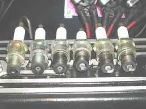
Before the car even had a chance to cool off from the trip I pulled the spark plugs. Number six (left side of photo) had been running rich but leanest was number two? I decided to again swap around injectors. Number six injector was set aside to move the leanest injector to the six location. The others followed suite moving lean ones to richer spots etc. Substituting for the old number six injector was a spare now placed into the number two cylinder. Still awaiting the starter bushings to arrive. By the way, we got 19.8 mpg on the Stowe trip.
September 28, 2003. I forgot to mention that on acceleration the car smokes. Not just black smoke from too much fuel but also blue smoke 🙁 If you really stand on it you REALLY get smoke! A compression test revealed cylinder readings between 130 and 140 psi except number five that reads a low 118psi. These are the original rings from 1975. Looks as if this winter will be a good time to freshen the lower portion of this engine. Along with rings and bearings a new cam will be fitted. Last week Aaron and I purchased two parts cars so I’m hoping to rebuild the lower half of one of those engines. In fact I hope to have it done and ready to swap this coming Spring when the car returns from storage. I’ve about a month of playing before it goes away for the winter.
Other winter projects on my list are to build another intake with the injectors near the cylinder head on the runner tubes, add a cam sensor allowing for true sequential injection, explore adding a supercharger or turbo (anyone want to trade my 1971 8.5:1 head for a low compression 1975 or 1976 7.5:1 head?), and a dozen minor projects. Anyone interested in experimenting with a low cost TR6 TBI fuel injection system (complete for under $1,000)?
October 30, 2003. For the past month I have been busy stripping two parts cars, adjusting rear camber, and experimenting with the fuel injection settings. I found that for some unknown reason an unsucessful experiment retarding the ignition was never reversed so recently under acceleration the timing has been 6 to 8 degrees less than it needs to be. That certainly helped matters. As far as smoking there as been progress there too. Under hard acceleration, vacuum drops off and the MAP sensor signals that the engine is under high load. Well the fuel map at higher rpm was way too rich adding as much as an additional 25% fuel! That was a lot of the smoke seen when the car was floored. Still some blue oil smoke but not much at all.
Another set of injectors has just been installed. This is a used set from a 4.0L Jeep straight six rated at 19lbs of fuel per hour. The VW set is rated at 18.75 so no adjustments to the fuel map was made. As these came from a six cylinder engine there are no spares. When first installed the car started right up but had a bad skip because number one injector wasn’t firing at all. With the engine running I heated the injector with a heat gun and it finally started clicking. Experimenting with the Color-Tune clear spark plug it was obvious that although it was now firing it wasn’t delivering much fuel. Number one cylinder only fired every six or seven revolutions. Without a spare I decided to try cleaning the injector. After pulling it from the manifold, a rubber fuel line was clamped over the output end of the injector. The hose filled with injection cleaner than pressurized with 35psi of air. Connecting the injector to a 12V battery would fire it forcing injector cleaner through it in the reverse direction. Hopefully it would blow out any dirt and clear the little tiny filter at the inlet of each injector. The cleaning has been a success and she is running quite well.
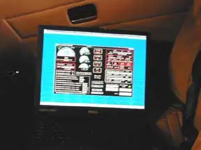
Too bad this photo came out so dark but it is of a laptop sitting on the passenger seat monitoring engine functions. It is absolutely amazing how much data is available and how many variables can be adjusted!
Recently Electromotive released a new firmware update and software revision. I have been reluctant to do the update as I want to drive the car as much as possible before going to storage. Today I called Electromotive about an oscillation caused by the idle air control motor. At times the IAC would start wild oscillations so it has been disconnected. As the temps here in Maine fall the IAC becomes more important as it will idle the engine up on cold starts. The update solved the problem. I now have it set to idle at 800rpm when warm and up to 1400rpm when cold. Too bad time is running out, I have another four profiles ready to try out.
Over the winter I’ll post updates from time to time. November 2003.
July Throttle Body Injection Conversion
A TR6 distributor with two vacuum chambers has been converted to operate as a GM electronic distributor. Both vacuum chambers have been removed and discarded as they will no longer be used. The distributor was disasembled and the points, condensor, counter weights, springs, and moveable top plate put away just in case the process ever needs to be reversed. The upper shaft that rocks back and forth with the mechanical advance, had it’s cam that operates the points turned down to accept a reluctor from a Chrysler slant six distributor. A chrysler pick was also fitted. Soon a GM control module will be fitted beneath the distributor.
Are wondering why convert the distributor? There are several adavantages, the prime one is that the new TBI computer will now be able to control advance, therefore ignition timing will be programable. This change will also allow “Limp home mode” in case of a computer failure. Better yet the timing can be optimized for max performance, be extremely reliable, and you never need to bother with points again. Still looks stock, uses the original TR coil (or could be upgraded), and runs the mechanical tach.
On going Multiport Fuel Injection
May 11, 2004
On the other fuel injection front, the multi port TEC3 system, there has also been some progress with the car now running full sequential injection. Check out the neat little cam sensor allowing the system to be updated to sequential. See: Cam Sensor
On a down note, I have to finally admit that the intake manifold design is flawed. There is just no way to balance fuel flow to each cylinder. As it now stands the front cylinders run lean while the rear run rich. My hope was that by running a sequential system, cylinders could be trimmed to balance the flow. Even with the ability to alter injector pulse times by 15% plus or minus (it allows a whopping trim of a 30% between high and low cylinders!) no go. The injectors need to be moved onto the runners, no question about it. The injectors have been moved but the updated version is not quite done yet. The picture below shows test fitting a set of injectors to the reworked manifold.
Update May 30, 2004
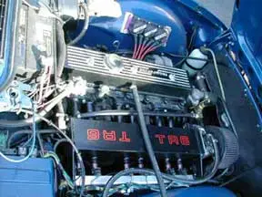
As you can see from the photos, the injectors have been moved and the manifold reinstalled. Very pleased to say that the injectors are now flowing much more evenly. Because of the change more tuning is required especially the area of hard acceleration which is now running rich. Evenly, but rich. Anyway this Memorial Day weekend will be spent fine tuning and I expect to have things very well sorted out within the day.